|
|
|
|
|
RECONNOITRE
RECONSTRUCTING THE 1954 ROUEN FLYING DISK
by Martin J. Powell
[This article first appeared in 'UFO Magazine' (UK), November/December 1997 edition]
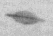
The flying disks seen in the McMinnville (1950) and Rouen (1954) photographs are renowned amongst UFO researchers for their remarkable similarity. A considerable number of features can be seen on the Rouen disk in particular (Figure 1 upper) and they are sufficient enough in number so as to attempt to draw up a plan and profile of it. In this article I have attempted to produce such a plan, and have detailed the various steps required to produce it.
There are clearly limitations to the amount of detail that can be shown on the final drawings. It cannot display any detail of the underside, for example, since this only appears in shadow in the McMinnville Photo 1, and it is not seen at all in the Rouen picture.1 The drawings can only show perhaps 60% of the disks upper surface area with any accuracy, mostly of the rear, since none of the photographs show the disk from the front. Consequently the frontal profile can only be speculative, based upon other details visible in the pictures. To the best of my knowledge, this is the first time an attempt has been made at drawing up such a detailed plan of a flying disk, based as it is on two of the most credible photographic cases in UFO history.
|
|
|
Figure 1 (Upper) The Rouen flying disk, photographed in 1954 (click for larger image). (Lower left) The flying disk photographed at McMinnville, Oregon in 1950. This is from Photo 1 and it clearly shows the disk to be circular in plan, and (Lower right) from Photo 2, in which the resemblance to the Rouen disk is striking (Reproduced from 'The UFO Casebook', Orbis Publishing Ltd, 1984) |
The Reconstruction
The Rouen image used for the reconstruction was first scanned in to my computer software using the scanners highest resolution mode of 400 dots per inch. Since it is seen banking to starboard (right) the image was then levelled to the horizontal.2
All points on the disk were referred to by their pixel co-ordinates in the computer software. The image measured 1042 pixels across. The distances between the pixel points of various features were converted into proportions of the disk width.
For the sake of easier plan construction, I thought it would be convenient to adopt a diameter for the craft. This has obviously been a point of contention over the years, so I considered that the best way to tackle this was to look at various estimates that had been made by previous researchers and take the most commonly agreed figure. I settled on a value of 25 metres, this giving the best overall agreement between the estimates.3
Using the proportions obtained via the pixel points, the approximate physical dimensions of the features were then determined, based on the assumption that the disk was 25 metres in diameter. These measured features could then be put in place on the proposed plan.
A couple of deductions could be made from the outset, without having measured anything. The McMinnville Photo 1 shows the disk from below, and it is clear from this picture that the plan of the disk is circular. Also, in both the McMinnville Photo 2 and the Rouen photo, the disk is seen almost edge-wise on to the line of sight. These pictures imply that the base of the disk would be flat when seen in profile. These two observations alone provided a sound framework for the drawing up of the plan.
The Rouen disk is seen in the photograph from behind and slightly to port (left). The first problem was to determine the angle at which it was being viewed relative to its longitudinal (roll) axis. This was largely a matter of trial and error, and I used two very different methods to try to find it.
The main indicators of the viewing angle were the distinctive vertical structure (or tail-fin) and the rear slope, both clearly visible in the photograph. The rear slope appears to originate from the central region of the disk, and it supports the tail-fin. I constructed a simple cardboard wedge to represent the rear slope, and I guestimated the slope angle at 30° to the horizontal. I fixed the wedge to a flat sheet of paper and, using the photograph as a backdrop, I viewed the slope obliquely until I determined a range of viewing angles which seemed to match that of the photograph. This method suggested a viewing angle of 24° ± 2 relative to the disks longitudinal axis.
The second method was more exacting and involved computer processing. I derived a series of simple formulae which translated selected points on the slope on to a theoretical plan. The computer model took three values as arguments: the rear slope angle, the viewing angle relative to the disks longitudinal axis and the apparent angle of the rear slope measured relative to the horizontal plane of the photograph. The latter value was fixed whilst the other two were able to vary. A co-ordinate system was devised having its origin at the lower left corner of the slope, located with as best precision as possible. The points were then translated from the theoretical slope into a horizontal plane and rotated clockwise by an amount equal to the viewing angle, in order to align the disks longitudinal axis with the vertical axis of the plan. The points outlined the features on the rear slope, and they could then be marked up in their correct proportions on the plan. The viewing angle was adjusted until the features on the final plot matched those on the photograph as closely as possible. The viewing angle derived using this method was 19°.
|
|
In order to construct a side profile of the craft I needed to determine the angle of the rear slope relative to the disks base line. The computer model suggested an angle of 18°.4, the error range being in the order of several degrees. Allowance had to be made for the fact that the disk is in a slight climb, perhaps around 7° to the horizontal.4 The rear slope melds into a curve around the sides of the disk, and it extends rearwards where it probably levels out slightly as it adjoins the rim.
The Platform
On the Rouen photograph the tail-fin is located on a supporting 'platform' which has a much lighter shade than the surrounding slope. A very obvious and peculiar feature of the platform is its irregular outline. I wanted to draw this as accurately as possible on the plan, and I used both the cardboard wedge and the computer model to reconstruct its shape. In the case of the wedge, I drew the outline of the platform directly onto the wedge while viewing it at the appropriate angle, using the photograph as a backdrop. The shape of the platform obtained using both methods was remarkably similar. The platform proved to be asymmetrical about its centre-line, the tail-fin occupying only the port half of it.
The Tail-fin and Nodule
This was one of the most difficult aspects of the reconstruction, since the shallow viewing angle prevents a good view of the tail-fin. The shape of the base of the tail-fin was derived by selecting a number of points which defined it (only the port side is seen in the photograph) and applying these to the computer model. According to this model, the thickness/chord ratio of the fin (i.e. width to length) varies substantially depending upon the viewing angle and the angle of the rear slope. The shape that was eventually selected was the one which best seemed to match that in the photograph. Unfortunately the point at which the trailing edge of the fin adjoins the platform is not clearly seen in the photograph since much of this region falls into shadow, the sun presumably shining from the left side of the picture. Furthermore the quality of the image is not good, so I had considerable difficulty in discerning the true outline of the fins base. I concluded that the thickness/chord ratio of the tail-fin was probably around 35% or less. During the reconstruction the tail-fin height was adjusted so that it stayed in proportion to the width of the body as it appears in the photograph.
A further complication arises because the leading edge of the fin cannot be seen clearly in the picture, so it is not possible to determine precisely where it originates from the body of the craft. In this case I had to estimate where the front of the tail-fin originated, and the computer model produced a side view of the fin which reflected this assumption. I also noted from the pixel measurements that the slope angle changes approximately half way down the frontal section of the fin, and I have also shown this in my reconstruction (Figure 3). Clearly then, the shape of the leading edge of the fin is speculative, and it only approximates to its true appearance. The trailing edge, on the other hand, is more accurately reconstructed, and it is evident from the photograph that it slopes forward at a sharp angle.
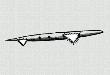
Figure 2 A conjectural reconstruction of the Rouen disk viewed (upper) from the front and (lower) from the rear (click for larger image). Compare this with the picture in Figure 1 (upper). |
|
|
|
||
|
|
One of the most important findings in my study of the craft came about whilst examining the location of the tail-fin in relation to the rear slope. In the Rouen photograph the tail-fin is clearly located behind the centre point of the disk. Since the craft is viewed from the left side, we would expect the tail-fin to occupy a position greater than half-way across the disk, measured from the extreme left edge of the disk. Instead it occupies a position around 0.46 times the disk width, i.e. less than half way across (which incidentally, holds true for both Rouen and McMinnville disks).5 The inescapable conclusion was that the tail-fin was positioned away from the central axis of the disk. It was offset to the port side, somewhere in the region of 0.04 times the disk width. For a disk with a diameter of 25 metres the tail-fin would have been offset to port by at least 1 metre. Such asymmetry is certainly a peculiar design feature, although it is not unique in the history of aviation.6
The nodule at the top of the tail-fin can be seen in both the Rouen and McMinnville photographs, but its shape is unclear. The most uncertain aspect is its length, since it is considerably foreshortened in the photograph due to the shallow viewing angle. In my reconstruction its width and height have been kept in proportion with the tail-fin, but its length has been largely guessed. The nodule is slightly wider at the top than the bottom, and in the Rouen photograph it appears to slope towards the rear, perhaps at the same angle as the rear slope.
Surface Markings
The Rouen disk seems to be unique in displaying surface markings. They are practically invisible in the McMinnville photographs owing to their poorer quality. Apart from the platform already described, two distinct markings can be identified.
A lighter shaded strip, resembling an elongated window or perhaps a simple stripe decoration, can be seen on the port side of the disk. It also appears on the starboard side, although it is nowhere near as clear. Its endpoints appear differently on both sides. On the port side it seems to end in a point, whereas on the starboard side it is rounded. I have shown this in my reconstruction, and I have assumed that the stripe extends all the way around the front of the disk uninterrupted (Figure 2 upper). This feature also seems to be asymmetric when viewed in plan.
|
|
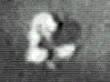
Figure 4 The marking on the tail-fin of the Rouen disk (click for larger image). (Left) in the original image and (right) stretched horizontally by a factor of 2.5. This approximates to how it would appear if it were viewed directly from the side. What is this insignia? |
|
|
A much more revealing feature appears on the tail-fin. Again, the shallow viewing angle prevents a clear view of it, identification of which could help determine the disks origin. In this case I decided to try a further experiment. Assuming the viewing angle to be 19° and estimating the angular size of the marking, I calculated that if I were to stretch it horizontally by a factor of around 2.5 to 3 times it would give an idea of what it might look like when viewed directly from the side.7 The result of this experiment is shown in Figure 4. The marking certainly looks artificial, being almost symmetrical about its centre-line, and it is not likely to have been the result of a film flaw or sunlight reflecting off the fin. Its interpretation will inevitably vary from reader to reader, but I thought it resembled an aircraft or an arrowhead, and I have shown it as such in my reconstruction. Its position on the tail-fin has been accurately rendered, but it is not possible to determine how far forward the marking extends.
|
|
The Bubble Canopy
This is the most speculative part of the reconstruction, and it is included for completeness, although its existence is questionable. It results from a poorly resolved feature in the Rouen photograph. There appears to be a dome-shaped feature, darker than the background sky, ahead and to either side of the tail-fin. I have interpreted it as a bubble canopy, although of course I could be mistaken. Its highest point is obscured by the tail-fin, so I had to estimate its height using approximate pixel measurements on the computer software and subsequently converting this into a ratio of the disk diameter.
|
|
|
|
Figure 5 Conjectural plan of the Rouen disk (click for larger image). Note the asymmetric layout of both the tail-fin and the suspected cockpit canopy. |
The canopy could only be put on the plan once the tail-fin had been put in place, since this is really the only indicator of where the canopy might be located. My reconstruction implies that, like the tail-fin, it is offset from the centre-line of the disk, but this time to starboard. In this sense it effectively balances out the asymmetry caused by the tail-fin. The egg-shape of the canopy has been guessed, although it is largely based on the appearance of canopies in experimental aircraft of the same era, such as the Avrocar.
Owing to the platforms relative position on the rear slope, I projected its boundary forward across the roof of the disk, and speculatively mirrored its shape to surround the bubble canopy (Figure 5). This seemed a reasonable thing to do, since in the photograph the line of the platform sides lead over the roof and out of sight, and as they do so they are skewed towards the starboard side of the craft, i.e. leading in the direction of the bubble canopy.
Discussion
The drawings I have produced are effectively a best fit of all the features I have outlined. There is some inevitable distortion in translating a circular object on to a flat plan, a point particularly relevant to the side profiles (Figure 2 and Figure 3). I have shaded the diagrams so that they approximate to the shades as they appear in the Rouen photograph, and they help to emphasise the various surface features.
Having completed the drawings, I then checked to see how accurately they related to the Rouen photograph. I selected 27 points on the disk and determined their relative positions in both horizontal and vertical planes. I found that 78% of the points (over three quarters) lay within 3.2% of the disk diameter from their correct positions on the photograph. The remaining 22% of the points had a positional error of between 3.2% and 6.4% of the disk diameter. In other words, if the plan of the disk was 10 cm wide, no single point would deviate from its correct position by more than 6.4 mm.
If my interpretation of the dome-shaped feature as a bubble canopy is correct, I thought that this could provide some idea as to the size of the craft. There were a couple of ways to approach the question. I first searched through a comprehensive book detailing military aircraft of the period in order to determine the average height of a cockpit canopy.8 It turned out to be 0.58 metres, based on ten aircraft. Were this true for the Rouen disk, its diameter would be around 19.5 metres. The second approach involved allowing sufficient head-room for the pilot. In other words, what would be the smallest useable canopy size for the test pilot? Using an average sized head wearing a helmet, the minimum disk diameter would be around 9 metres. I therefore concluded that the disks diameter lay somewhere between 9 and 20 metres. The situation is of course complicated by the possibility of the cockpit containing two pilots, in which case the disk would be larger still. I think the disk is likely to have been on the smaller side, i.e. around 9 metres diameter, which seems a reasonable size for a research aircraft of this type. It is worth noting that the Trents believed the McMinnville disk to be between 6 and 9 metres in diameter.
I have not made any provision in my reconstruction for a propulsion system. The engine outlet is likely to have been located in the base of the disk, in which case it is only seen in shadow in the McMinnville photograph. If it was powered by jet engines mounted within the fuselage, the air intakes would probably have been either at the front or on the top of the disk, out of sight in the photographs. However, the first jet-powered VTOL (Vertical Take-Off and Landing) craft did not get off the ground until 1951.9 Any researcher looking into this case must address the question as to why the jet-propelled Avrocar was such a failure, when the McMinnville-Rouen disks had been flying around, apparently without difficulty, nearly ten years earlier.
I believe the plans to be reasonably accurate representations of the craft in question. They are only suggestions for a solution and they cannot be regarded as definitive, at least not at the present time. They do however serve to show the most important elements seen in the photographs, namely the sloping rear, the irregularly shaped platform, the offset tail-fin and the surface markings.
There are still a few aspects which seem problematic and will require further attention, particularly regarding the location and shape of the tail-fin, but since all elements of the craft are inter-related, any small amendments will require a complete revision of the plan. I will continue to refine these drawings until the positional errors are acceptably low. A reconstruction in the form of a three-dimensional model would be desirable. Only then will I be satisfied that the true appearance of these enigmatic craft have finally been revealed.
Copyright Martin J Powell June 1997
The Rouen UFO Photo: Additional Information and Research (ca. 2004)
Many UFO investigators now believe that the Rouen photo was taken on 5th March 1957, and not 1954 as previously cited by many researchers (including myself). The error seems to have arisen after the incorrect date was given in a 1964 publication by NICAP. The British publication Flying Saucer Review (May-June 1957 edition) added that the photograph was taken "at 08.13 hours".
Details of the circumstances surrounding the photo have always been sketchy, however French UFOlogist Patrick Gross gives the following additional information on his website UFOs At Close Sight:
"Flying to intercept a mysterious radar reflection, an unknown French Air Force pilot photographed this craft ... over Rouen with his gun-sight camera. The UFO paced the plane for several minutes before speeding off past the maximum velocity of the French airplane".
An historical account of the Rouen UFO case has been published (in Acrobat Reader format) by Spanish researcher Vincente-Juan Ballester Olmos in a report entitled 'The Year 1954 in Photos' (FOTOCAT Report #1).
The photo's elusive background details, coupled with the fact that neither the source nor the photographic negative have ever been traced, has led many UFO researchers to doubt the photo's authenticity, or to reject its validity altogether. A predisposing factor in the debate has been its evident similarity with the earlier McMinnville disk photo, an aspect noted by many writers and researchers over the years. In an unpublished paper in 1990, CUFOS investigator Dr Willy Smith stated his belief that the McMinnville and Rouen photos "are one and the same, i.e. the Rouen photo ... is only a copy, many generations removed, of the Trent photo" (cited in the above Fotocat report).
However, American UFO researcher Bruce Maccabee, who has spent many years studying the McMinnville photos, believes that "the orientation [of the two objects] in 3-D space is different, i.e., the object in the Rouen photo is rotated somewhat from the orientation in Trent #2". If this is genuinely the case, it follows that the Rouen photo cannot simply be a copy of the Trent photo (Maccabee's discussion of the Rouen photo forms part of his McMinnville photos analysis; see section entitled 'The Rouen Photo').
A further discussion of the photo (Nov 2004) appears as part of NICAP's Rouen UFO photo case directory.
The McMinnville & Rouen Disks: A preliminary comparison of visible features
High quality enlargements of the McMinnville disk in Paul Trent's second photograph appear to show the lighter-coloured tail-fin 'platform' which is so clearly seen on the Rouen disk.
The images on the right were taken from two different sources, and in both cases the 'platform' can be discerned if the pictures are examined carefully. All pictures have been lightened by computer software, but apart from this, no other changes have been made to these images.
Of particular note, however, is the fact that the 'platform' and the tail-fin appear to be at different orientations, as Maccabee has suggested (differing in a horizontal sense by about 25º). Both disks are seen from the rear, the Rouen disk showing the port (left) side of the tail-fin, whilst the McMinnville disk appears to show the starboard (right) side of the tail-fin.
|
|
|
|
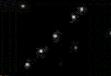
These images appear to show the presence of a 'platform' on the McMinnville disk, similar to that seen on the Rouen disk. The red line marks the apparent outline of the 'platform'. A - The Rouen disk; B & C - the McMinnville disk in Paul Trent's second photograph (from Bruce Maccabee); D & E - the McMinnville disk (from the UK Sunday Dispatch newspaper, dated July 9th 1950, featured on the UFO Magazine (UK) CD-ROM entitled The Folder). |
There are other reasons to question the notion that the Rouen photo is a copy of the Trent photo. The curvature and inclination of the slope at the sides of the two disks appear to be different. The question must also be asked why the Rouen image contains such detail, when it is supposedly a multiple-generation copy of the Trent photo. Indeed, the Rouen disk appears to contain more detail than the Trent disk. A photographic reproduction will not show greater detail than its source image - unless of course, the Trent photo was re-photographed and manually retouched, resulting in the details that we see in the Rouen photo.
A more detailed examination and computer enhancement of the disk in Trent's second photograph is required before the similarities between the disks can be clarified with any certainty. The proportional similarities were the focus of my unpublished article entitled "Two of a Kind?" written in 1996.
(Note added August 2004)
REFERENCES
1. For the purposes of this discussion, the McMinnville photo showing the underside of the disk is referred to as Photo 1, and that showing the rear view is Photo 2.
2. The image used in the analysis was from Peter Brookesmith (ed.), UFO Casebook, Orbis Publishing, London, 1984, pg. 42. It was scanned using Logitech FotoTouch software, and pixel measurements were made using the Microsoft Windows Paintbrush facility.
3. The diameter estimates were by Paul Trent (McMinnville UFO witness), William Hartmann (Condon Committee), Bruce Maccabee (research physicist), and Ground Saucer Watch. The diameter so obtained was 18 metres ± 12.
4. To determine this angle I first measured the relative proportions of the ellipse presented by the disk, and then used simple trigonometry on the principle that 0° = a circle seen edgewise on and 90° = a circle seen face on.
5. A handsome enlargement of the McMinnville disk in Photo 1 can be seen in Peter Brookesmith, UFO, The Government Files, Blandford Press, London, 1996, pg. 52. The observations given here were obtained from this picture. The nodule is visible in this photo, and it again occupies a position 0.46 times the disk diameter from the extreme left edge of the craft. Judging by the proportions of the ellipse presented by its under surface, the disk is being viewed from below at an angle of about 22° or less, relative to the horizontal. Consequently in this picture we see the craft from almost directly behind and from below, inferring that the disk travelled practically in a straight line between Photos 1 and 2. Presumably it then banked to starboard and headed off into the distance.
6. The first aircraft to use an asymmetric layout was a German reconnaissance aircraft, the Blohm und Voss Bv 141, which first flew in 1938. Several variations were made on the design, but all types had the tail-fin, mounted on a boom, offset to the port side of the central axis and the nacelle offset to the starboard side. Blohm und Voss also experimented with asymmetric designs in their subsequent jet aircraft. See Tony Wood and Bill Gunston, Hitlers Luftwaffe, Salamander Books Ltd., London, 1977, pg. 135.
7. When attempting to reconstruct the possible appearance of the tail-fin marking I had to bear in mind the limiting resolution of the original photograph I had used. In other words, detail could not be resolved in between the dots which formed the original photograph. In my scanned image of the photograph, each dot in the photograph was about 6 pixels apart, so any features smaller than 6 pixels across could not be reliably measured. Fortunately all of the features in the reconstruction were more than 6 pixels across, so their measurements could be considered reliable.
8. Bill Gunston, The Encyclopaedia of the Worlds Combat Aircraft, Hamlyn, London, 1976.
9. In 1951 the Ryan Aeronautical Company "successfully hovered a [jet powered] device looking like an ashcan fitted with stilts" in Above and Beyond (The Encyclopaedia of Aviation and Space Sciences), Volume 13, New Horizons Publishers, Chicago, 1968, pgs. 2438 - 2444. This has quite a comprehensive account of the development of V/STOL aircraft.
|
|
|
|
|
|
 the Rouen flying disk and (Lower) two views of the McMinnville flying disk")